
Doyle DESIGN
The Doyle design office is the innovator behind the leading Cableless and Structured Luff Technology and where the limits of sailmaking are constantly tested.
Doyle Sails' central design team consists of highly qualified sailors who each bring different strengths. Our unique design software and tools are amongst the most advanced 3D modelling and airflow technology available worldwide.
One of the cornerstones of our sailmaking process is a sophisticated and thorough approach to design and engineering. Before any fibre gets laid or cloth is cut, we complete a detailed analysis of the boat, the rig and hardware to fully understand what will be required to make sails that will fulfill the customer's requirements.
“The design team led by Richard Bouzaid, put in a huge effort. If you want something different, something fast or an edge - it is best not to follow the crowd”.
- Alex Thomson, HUGO BOSS

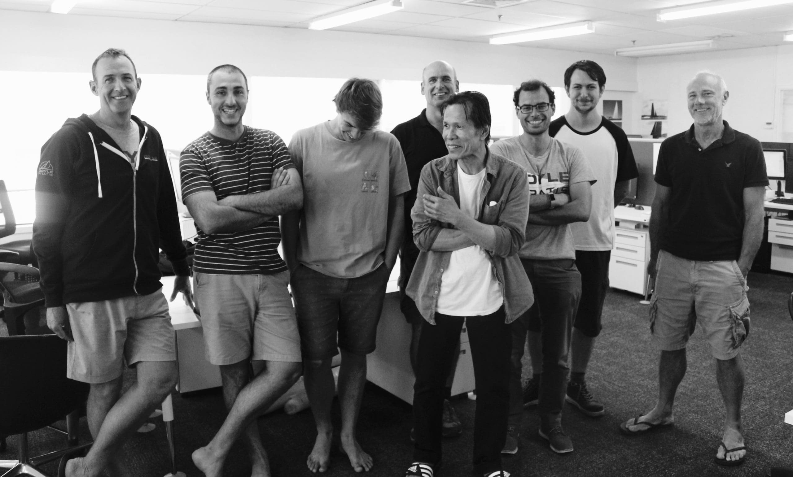
Richard Bouzaid
Design Director
David Armitage
Senior Designer
Alessandro Castelli
Designer

Jordi Calafat
Grand Prix Design
Andrew Lechte
Senior Designer
Nini Cirello
Designer

Justin Ferris
Grand Prix Design
Travis Meindl
Designer

Daniel Fong
Grand Prix Design
Tyler Doyle
Designer

Stefano Nava
Senior Designer
Dario Motta
Designer

COMPUTATIONAL FLUID DYNAMICS
Doyle CFD uses high-resolution simulations to optimize sailing yacht aerodynamics, hydrodynamics and structures. Our analysis and designs are driven by data from state-of-the-art Computational Fluid Dynamic (CFD) and Finite Element Analysis (FEA) simulations. Our simulations provide designers with much of the same data supplied by wind tunnels and tow tanks, and a lot more. We have experience analyzing and designing most major sailing yacht components from sails to foils. Doyle CFD was founded in 2011 to further develop computational tools and analysis techniques developed at Stanford University, NASA and Doyle Sails. Doyle Sails was one of the early adopters of this type of in-depth sail study and this technology plays a major role in the design of all Doyle superyacht sails.
Images are shown below display CFD and FEA studies on two of the world’s largest sailing yachts; M5 and Sailing Yacht A. On top is shown aerodynamic and hydrodynamic post-processing from a CFD based VPP study of M5 sail options. In the middle are fiber layouts from Sailing Yacht A’s mainsail, and below that stress plots from analyzing the sail and rig. On the bottom is shown a typical superyacht sail plan and to the right of that M5 sailing.
A CFD analysis begins by creating a geometric model of the mast, boom, hull, deck, sails and other features that are important to the flow around the boat. What geometry is included depends on the required level of resolution of the study. A structural FEA model begins by defining the geometry and structural properties of the mast, sails, boom, running rigging and their connections. Once the geometry and structural properties are defined fluid flow and structural loads are applied to the models. CFD simulations provide detailed information about the air and water flow around the boat as well as the pressure and skin friction on the sails, hull and foils. CFD simulations are used to optimize shapes. FEA simulations predict the state of stress and deformation in the sails, battens, mast and rigging and are used by designers to determine how strong structures need to be.
CFD and FEA simulations can be combined in a Fluid Structure Interaction (FSI) model, which combines a fluid flow solver and a finite element solver. FSI models are used to predict the flying shape of sails. The FSI solver performs the calculation using iterative steps in a loop process; for each loop the aerodynamic forces are calculated and then applied to the sail which deforms into a new shape. The new shape is then used in the next loop to recalculate the aerodynamic forces and then recalculate the deformed shape. The computation is done in this iterative form until the discrepancy between the deformed shape of the current step and the one of the previous step is reduced below a threshold.
Sail designers use sail strain maps that are produced in FSI or FEA models to analyze and to verify the structural behavior of the fiber layout. Highly loaded regions characterized by excessive strain are reinforced with additional fiber to better support these regions. Individual yarn strains are analyzed to determine where and how the loads are transmitted, so that the fiber layouts can be developed to control and optimize the shape of the sail. The sail design is tested through its range of use to confirm that no excessive strain is generated and the flying shape is optimized to suit each condition.
